Installing in an Air/Gas Sampling System
The recommended piping installation of a SHAW portable dewpoint meter depends very much on the application. Variables such as pressure, temperature, contaminants and sample flow should all be taken into account. The SHAW dewpoint sensor is robust and easy to use. However, the sampling arrangement for piping installation should ensure that the dewpoint sensor is not damaged by contaminants or liquid. Simple compressed air applications at atmospheric pressure may see the dewpoint sensor connected directly to a sample tap-off point on the piping installation line whereas high pressure applications with contaminants would require a more sophisticated sample arrangement.
The diagrams below show the key elements of any piping installation sample arrangement.
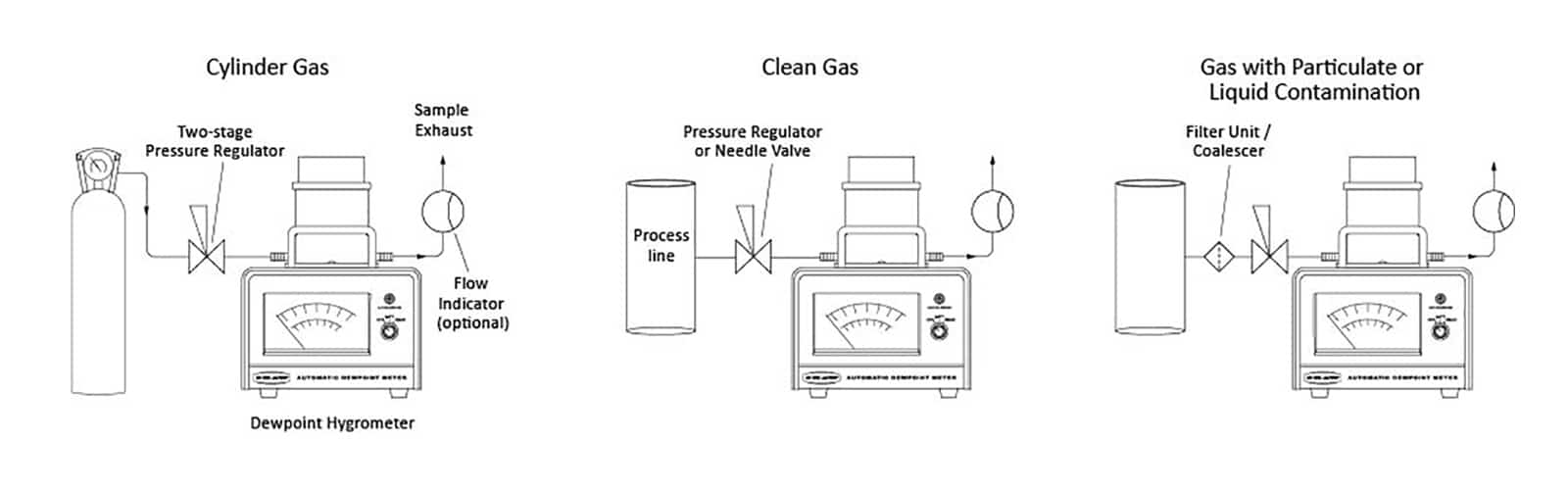
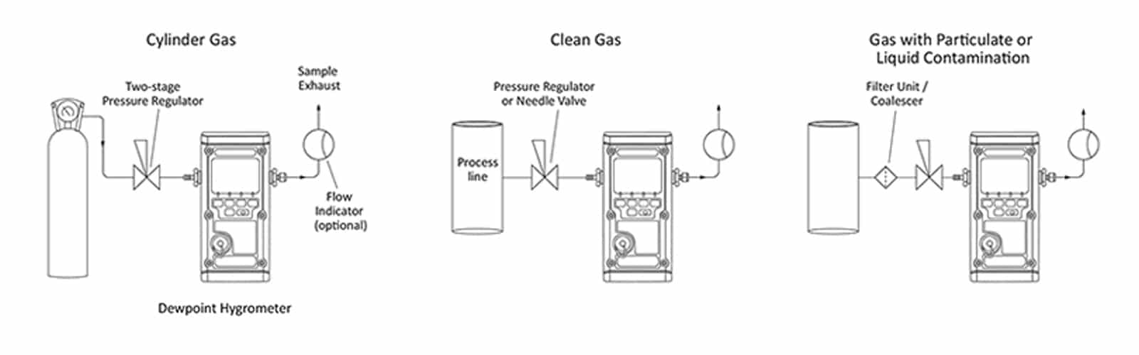
Simple compressed air applications may see the dewpoint sensor being inserted directly in to the process line whereas natural gas applications would require a more sophisticated arrangement.
Piping Installation Schematic
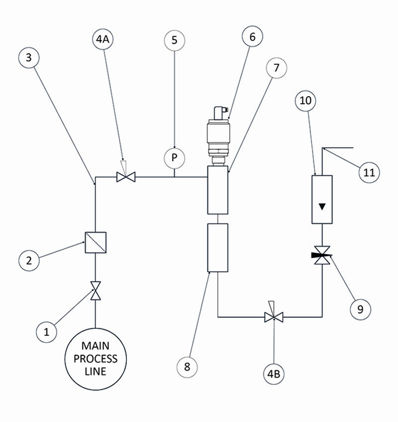
Piping Installation Schematic Component Index
- Sample Isolation Valve – This is a recommended item as it allows access to the sample system without interrupting the main process line.
- Sample Tube – This should be stainless steel for dry air or gas applications but copper or carbon steel can be used where wetter gases are to be measured. If any section of the sample tube must be flexible then PTFE should be used. In most cases, 3 mm OD (⅛”) is sufficient as it provides good system response time within minimum flow. 6 mm OD (¼”) tube can be used where pressure drops across the 3 mm tube are too high.
- Filter Unit – A filter unit is recommended when the samples are likely to contain particulate matter. If the air/gas sample contains heavy hydrocarbon condensate, the filter must be of the coalescing type with a drain. The filter unit should be positioned as close to the sample point as practical.
- Pressure Reduction Valve or Pressure Regulator – If the sample is to be measured at atmospheric pressure then the valve 4A should be fitted and 4B omitted from the system. If the sample is to be measured at full line pressure and the exhaust vented to atmosphere then valve 4B should be fitted and 4A omitted from the system. If measurements are to be taken at full line pressure and the sample is to be returned to a part of the main line or a vent, which is at a pressure higher than atmospheric and the input to that line needs a controlled pressure then both 4A and 4B will be required.
- Sample Pressure Gauge – This is not a critical part of moisture measurement but may be required if dew point/frost point measurements are to be made at higher than atmospheric pressure.
- Measuring Transmitter – Dewpoint Transmitter with Connector, General Arrangement
- Transmitter Holder – Transmitter Holder General Arrangement
- Desiccant Chamber – This item is required when the sampling is to be intermittent. When installed it prevents the ingress of wet air to the sample system, while the sample is not flowing, improving the response time.
- Flow Control Valve – This can be a separate item or combined with the flow indicator.
- Flow Indicator – The recommended sample flow is 2 to 3 litres/min.
- Sample Exhaust – The exhaust can be vented to atmosphere or returned to the process line as discussed above.